Autocad Drawings for Fiber Plant
Published by: Rick France - Solutions Engineer
A Hagerman & Company customer called needing to create Equipment Fabrication Drawings early in the design process and the client wanted to use the Orthographic feature of AutoCAD® Plant 3D to accomplish this. The customer wanted to have these drawings developed before creating any General Arrangements.
A problem arose when they started to work on the General Arrangements and began moving equipment around, making changes to equipment such as nozzle locations. Once the Ortho Views were updated, the equipment would "disappear" and the Ortho Views would then have to be recreated. The result was quite a bit of re-work and cleanup that added many hours to the project. It's understandable why this would happen since the equipment was moved in the layout from which the Orthos were created to a new XYZ location.
The customer tried creating the equipment as individual drawings and used those to create the Orthos, externally referencing each equipment drawing into the General Arrangement. It was discovered, however that this method would not work due to Plant 3D's requirement of all XRef's being attached at 0,0,0. The next idea was to duplicate the equipment in the GA to a separate equipment drawing, but since two pieces of equipment cannot share the same equipment number that too failed. Assigning different equipment numbers was not an option for obvious reasons, so the customer was stuck with having to live with this issue or create the fabrication drawings with vanilla AutoCAD. I first told the customer this was the only option unless they waited until after the GA's were completed to create the fabrication drawings. Of course, that was not an option they could live with either.
One week later, I had the same request from one of my students in a Plant 3D Training Class and I began to think outside the box and came up with a solution that satisfied both clients. As a result I now want to share this idea with everyone just in case it is something you have been struggling with as well. This solution is quite simple and requires a secondary project for the Fabrication Drawings and the use of Equipment Templates.
To begin, I have created my main project and placed a Heat Exchanger in my General Arrangement.
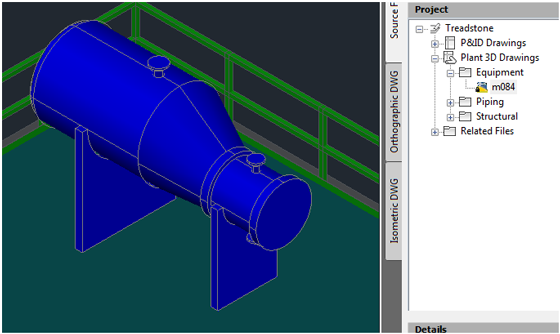
In the main project, I will create my Structural, Equipment & Piping Layouts, as well as Isometrics and Orthographic Drawings, with the exception of the Equipment Fabrication Drawings. My Project is named "Treadstone".
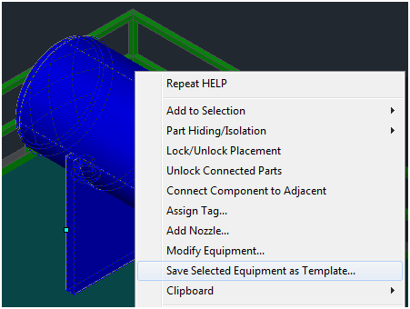
Before I create my secondary project, I will select the heat exchanger, right click and select "Save Selected Equipment as Template…".
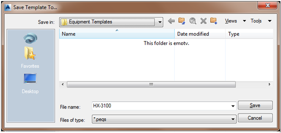
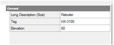
The "Save Template To . . ." dialogue box automatically goes to the location of the Equipment Templates as it is set in the Project Settings. I will use the Equipment Number (HX-3100) as the name of the template file to make it easy to know which template goes with which piece of equipment. I will need to create a unique template for each piece of equipment that I will be creating a Fabrication Ortho Drawing of.
Select Save to get back to a Command Prompt in Plant 3D. Then Save and Exit the drawing.
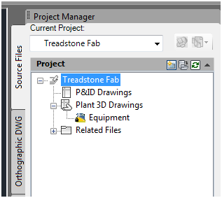
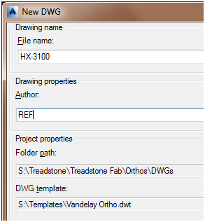
For the Fabrication Drawings I will create another Project named "Treadstone Fab". However, I will create this as a sub-directory of the main project by Specifying the directory where the program-generated files are stored as the location of the main project. In my case I will use S:\Treadstone per the dialog box below and wind up with a folder named S:\Treadstone\Treadston Fab\ for this secondary project. This will keep all of my project files in the same folder structure within Windows.
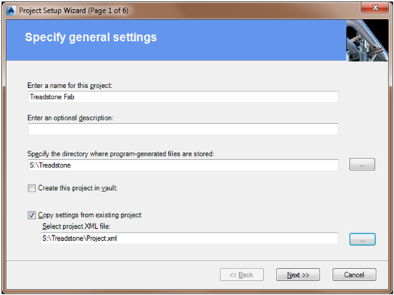
In addition, I will use the "Copy settings from an existing project" option and select the Project.xml file for the main project. This will ensure that all my properties are the same in both projects as well as title block information. Keep in mind that if you make a change in the main project settings you may need to make the same change in the secondary project if it pertains to equipment or title block information.
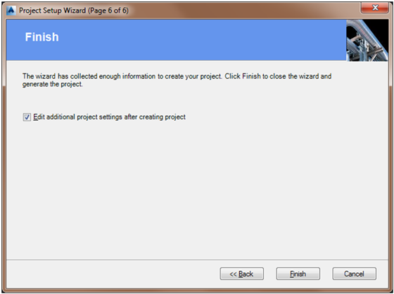
Since you are copying a project XML file, everything will be pre-selected for the next few screens as you click on "Next". On the final screen, enable "Edit additional project settings after creating project" before you click Finish. If you miss this step just open the Project Settings after the new project is created.
This next step is key to making this work. In the Project Setup dialogue box, locate Paths in the tree under Plant 3D DWG Settings. Change the Equipment templates directory to the exact same location that it is set to in the main project. This will keep us from having to constantly copy templates from one project to the other thus cutting down on mistakes. Select OK to save your changes and exit out of the Project Setup.

Optionally, since the main project had some sub-folders for Equipment, Structural & Piping that I do not need in this project, I removed them from the Project Manager. I will create and open a new drawing named Equipment.dwg. I eventually intend to place every piece of equipment in this drawing randomly never to be moved or relocated.
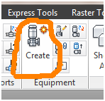
On the Equipment Panel of the Home Tab, select Create.
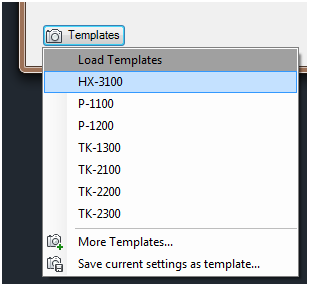
In the Create Equipment dialogue box, down in the lower left corner under Templates, you will find a list of every piece of equipment you have saved in the main project. Select HX-3100 to load the exact same heat exchanger into the project. Assign the appropriate Tag, HX-3100, select Create on the bottom right of the dialogue box and place wherever your heart desires.
After placement, feel free to change any layers you might need to. After placing all the equipment that is required, save and exit the drawing.
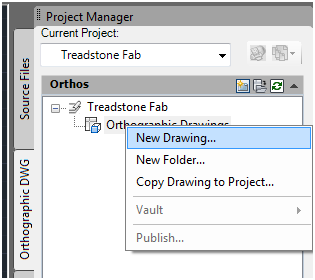
In the Project Manager on the Orthographic DWG tab create a new Ortho Drawing for the Fabrication Drawing. I would suggest using the Equipment Number for the drawing name but you can use whatever name you prefer.
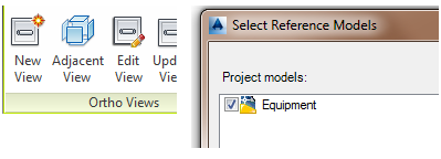
On the Ortho View Tab, Ortho Views Panel select New View. Then select Equipment as your Reference Model and Click OK.
Select your View, size your Ortho Cube and select your scale factor. For the best results, use All Hidden Lines for your Output Appearance. Once satisfied, select OK to return to the Ortho Drawing.
Read more
Source: https://knowledge.autodesk.com/support/autocad/learn-explore/caas/simplecontent/content/autocad-plant-3d-orthographic-equipment-fabrication-drawings.html
0 Response to "Autocad Drawings for Fiber Plant"
Post a Comment